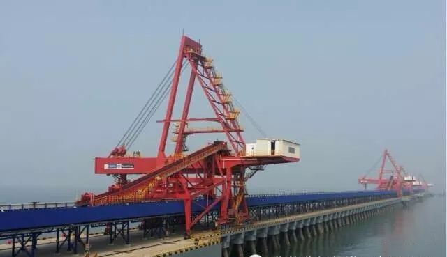
Overview: With the development of the national economy, the volume of bulk dry bulk cargo such as coal, ore, sand, bulk grain, fertilizer, etc. in water transportation is increasing year by year, and the tonnage of transport ships is becoming larger and larger, so the loading and unloading equipment is also developing in the direction of large, efficient and low energy consumption. Port transport machinery plays a key role in the specialized terminal of bulk cargo, and belt conveyor, as one of the important components of port transport machinery, lays the foundation for the reliable, efficient, energy-saving and economic operation of port transport machinery. Combined with the process requirements and characteristics of port transportation machinery, the design points of port belt conveyor are highlighted and the application situation is briefly listed.
(I) port transportation composition and typical process:
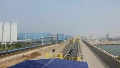
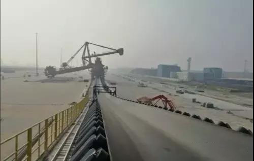
Port transport machinery mainly includes continuous transport machinery, port handling machinery, auxiliary equipment three categories. The continuous conveying machinery is mainly belt conveyor;
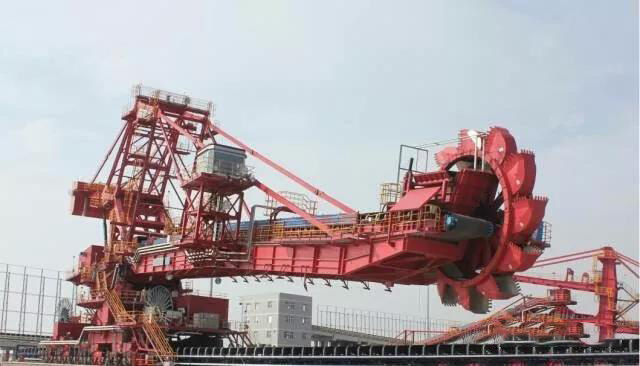
Loading and unloading machinery mainly includes all kinds of ship unloaders, ship loaders, car unloaders, car dumpers, stacker-reclaimer, etc;
Auxiliary equipment mainly includes storage, feeder, metering device, iron removal device, various protection devices, etc.
According to the different uses of the port, based on the belt conveyor, the configuration of different loading and unloading machinery can be built into a considerable capacity of the import and export terminal loading and unloading conveyor system, a system generally has several processes, the typical port loading and unloading conveyor process is the following:
1) Unloading (ship) ----- stacking process;
2) reclaim ---- loading (vehicle) process;
3) Material reclaim-delivery process to the user;
4) Unloading (ship) --- loading (ship) straight take process;
5 Unloading (ship) --- direct transfer process to the user unit;
(II) port belt conveyor design requirements:
(1) Determine the reasonable reprint mode and put forward the requirements of feeding device and unloading device;
(2) straighten out the relationship between the belt conveyors of the conveying system. According to the starting sequence, the feeding conveyor moves first, and the stopping sequence is the feeding conveyor stops first. When the parameters of the conveyor are different, the requirements for starting and stopping time are put forward through this relationship;
(3) When the above start-up and stop sequence requirements cannot be met, it is necessary to consider adding a buffer silo between conveyors to improve the adaptability of the system and the operation rate of the system;.
(4) Environmental protection requirements, for the case of large dust to consider the use of closed transport or set up the necessary dust and other equipment;
(5) Standardization and generalization of parts and components and availability of wearing parts;
(6) Select the conveyor with the inclination angle adapted to the process requirements. According to the material characteristics and working conditions, the conveying inclination angle is allowed to be 15 ° for upward transportation and 10 ° for downward transportation;
(7) The tape sag between adjacent idlers shall not exceed 1%;
(8) When the belt conveyor is braked, the maximum working tension should not exceed 1.5 times the working tension during normal operation;
(9) The design of the curvature radius of the concave arc section of the belt conveyor should meet the requirements of no-load starting, the belt does not break away from the roller, and does not produce the phenomenon of streamer;
(III) port belt conveyor design content and basis:
The design content mainly includes conventional belt conveyor design, dynamic design, resonance avoidance design, component design, electrical and control system design, etc. Before the system design, the requirements for equipment should be fully understood, mainly based on the conveying volume. When the material flow is uniform, it can be given directly. Generally, it should be designed and calculated according to 10% of the overload capacity, unless otherwise agreed. Detailed dimensions of the transmission line, mainly including the maximum length, inclination angle, lifting height and connection size. The nature of the material; the main parameters are loose density, resting angle, material particle size and maximum block degree, material humidity, wear, adhesion and coefficient of friction. Working conditions and environmental conditions; ambient temperature, place of use, environmental protection requirements, etc. Feeding and unloading methods, running time, working days, service life and other requirements, according to the design requirements, in particular, carefully weigh the selection of the maximum sag, simulated friction resistance coefficient, conveyor belt and roller friction coefficient, conveyor belt safety factor and other parameters that have a great impact on the stability, safety and efficient operation of the conveyor system.
(IV) port belt conveyor components configuration and selection:
(1) Reasonable arrangement and configuration of driving parts
a. Drive arrangement:
The drive device is generally not arranged in the transfer machine room and choose to arrange on the ground, in order to reduce the specifications of the machine room, while the reducer is preferred to use parallel shaft type, saving system infrastructure costs.
B. Configuration of drive unit:
Following the principles of reliability, high efficiency, economy, energy saving and convenient maintenance, the port belt conveyor preferably adopts the driving mode of ordinary low pressure (or high pressure) plus hydraulic coupling. The general principle is to divide according to the driving power of the motor and the captain. When the motor power N≤ 150KW, the short-distance belt conveyor adopts ordinary torque-limited hydraulic coupling. When 150300KW, the long-distance belt conveyor is selected, and the extended auxiliary cavity and the side auxiliary cavity are selected to further extend the start-up time, so as to obtain a more ideal start-up curve.
For long distance (L>1000m), large capacity port belt conveyor can give priority to the choice of frequency conversion speed regulation or other soft drive mode, which to choose the frequency conversion speed regulation drive mode more, mainly because the frequency conversion speed regulation has the following advantages:
1. The AC frequency conversion speed regulating device has the characteristics of wide speed range, reliable control and obvious energy saving effect. It is easy to realize the automatic tracking of the braking speed curve and can provide ideal controllable starting/braking performance.
2. The conveyor can be controlled to start and brake according to the set "S" speed curve to meet the requirements of dynamic stability and reliability of the whole machine.
3. The power balance between multiple drive motors can be realized with high precision.
4, can adapt to the frequent start and stop requirements of the port transportation system.
5. The variable frequency speed regulating drive device can also provide low speed belt inspection speed, which is convenient for maintenance and overhaul.
For high-power belt conveyor, double-drum multi-motor drive should be used to reduce the maximum tension of the system. Thus, under the premise of ensuring safety, the selection of tape models can be reduced and equipment procurement costs can be saved.
c. Selection of simulated friction coefficient and motor surplus coefficient:
In the process of driving power calculation, the reasonable selection of simulated friction coefficient and motor reserve coefficient has a great influence on the calculation results, and the appropriate coefficient is selected to ensure the smooth operation of the conveyor system and meet the requirements of energy saving and consumption reduction. On the premise of providing high-quality products and good installation and construction conditions, the recommended value of comprehensive friction coefficient is:
Conveying material is coal: simulated friction coefficient: f = 0.020~0.022, conveying material is ore: simulated friction coefficient: f = 0.022~0.025. The motor surplus coefficient can be taken as K = 1.05, which must be verified by calculating the additional power for the full load start of the conveyor to ensure that the final installed capacity can ensure the smooth start of the full load.
(2) Calculation selection and configuration of idler:
A. the selection of idlers mainly considers the bearing capacity and service life of idlers, and comprehensively considers the following factors: the size and characteristics of the load, the width and running speed of the conveyor belt, the working conditions, the working system of the conveyor, the characteristics of the conveyed materials, the service life of the idlers bearing, the sealing structure of the idlers, the lubrication conditions, the maintenance system, etc. the selection of roller diameter should ensure that the roller speed is controlled within 550r/min.
B. the idlers of the bearing section of the port belt conveyor are generally configured according to the groove-shaped idler group and the groove-shaped forward tilting idler group 1:1, and the spacing between the idlers is 1.2m or 1m according to the density of the conveyed materials and the size of the transportation volume. The spacing of convex arc sections shall be 1/2 of the normal spacing, and the spacing of buffer idlers at blanking points shall be 1/3 of the normal spacing.
c. A transition idler group is set at the head and tail so that the tape can be smoothly grooved. The minimum transition distance at the head shall not be less than 2.6 times the bandwidth, and the transition distance at the tail shall not be less than the normal idler spacing. The return section shall be configured according to the parallel roller group and V-shaped roller group (or forward tilt) according to 2:1, and the return roller spacing is generally 2.4~3m. 7 sets of comb-shaped idler groups should be arranged near the head return section, 3 sets of spiral cleaning idler groups (generally referring to the trestle surface) should be arranged in the return section to the drum, and the return section should be matched with the anti-V-shaped idler group to prevent deviation, and 1 set should be arranged every 50m. Special attention should be paid to the selection of groove-shaped idler group plus two-way reversible up-aligning idler group and parallel lower idler or V-shaped idler group plus two-way reversible down-aligning idler group on the two-way running belt conveyor.
(3) Drum structure and process requirements:
The drum shaft shall be high-quality forged steel, and the wall thickness of the drum shall not be less than the standard requirements and shall be correspondingly thickened. The drum cylinder is of cast-welded structure, and the hub and the axle are connected by expansion sleeve. The weld between the hub and the flange must be a fully penetrating continuous weld. For the drum with cast welding structure, the material of the cast welding plate is cast steel, and the welding method of the cylinder is CO2 gas shielded welding. The split bearing seat is preferred. The thickness of the driving drum and the direction changing drum casting glue shall be thickened on the basis of the standard.
(4) Design and stroke selection of tensioning device:
Port belt conveyor tension forms are mainly vertical heavy hammer tension, heavy hammer car type tension, hydraulic tension. The elongation of the tape itself and the necessary installation allowance shall be taken into account in the design of the tensioning stroke. The recommended length of the tensioning stroke when using steel cord tape is shown in the following table:
belt conveyor
Horizontal length (m) Effective tightening stroke (m) Remarks
L≤ 300 0.005L 1.5B B is the bandwidth
300 0.0045L 1.0B B is the bandwidth
L>600 0.004L 1.0B B is the bandwidth
| belt conveyor Horizontal length (m) |
Effective tightening stroke (m) |
Remarks |
| L≤300 |
0.005L 1.5B |
Bfor bandwidth |
| 300<L≤600 |
0.0045L 1.0B |
Bfor bandwidth |
| L>600 |
0.004L 1.0B |
Bfor bandwidth |
(5) unloading transfer system design:
a. The discharge and transfer system mainly includes head funnel, three-way distributor, blanking chute, buffer centering device, guide chute, etc.
B. the unloading and reprinting system shall be designed according to the maximum flow rate and maximum block degree of the material to ensure that the chute does not block the material under any working condition; The section of the chute shall not be less than 4 times of the section of the material when the maximum flow rate passes through, the minimum size of the section of the chute shall not be less than the maximum size of the superposition of the 3 pieces of maximum block degree on the conveyed material, and the chute, and the inclination angle of the chute.
C. inspection doors shall be set at necessary positions of the unloading and transfer system, and the flange connection shall be sealed with soft rubber plates to prevent dust and suppress dust.
D. the three-way distributor must have heavy-duty switching function, and its structure can withstand the long-term impact of the maximum flow rate and the maximum lumpy material. the turning surface of the switching baffle must be isolated from the material to prevent the baffle from being stuck and to ensure that the baffle cannot freeze with the chute in winter. The torque selected for the electric (hydraulic) push rod of the baffle shall be greater than 2 times of the calculated torque.
e. The buffer centering device is arranged between the lower part of the chute and the guide chute of the lower belt conveyor, and shall be inclined in accordance with the conveying direction of the lower part, so as to buffer and prevent the impact and damage caused by high drop materials on the lower belt conveyor, and also have the function of centering materials.
F. the layout length of the guide chute shall not be less than 5 times of the bandwidth. there shall be enough space inside the guide chute for materials to pass through. the height of the guide chute shall not be less than the maximum size of 3 pieces of maximum block degree superposition. the guide chute and the conveyor belt can be sealed with anti-overflow skirt or whole wear-resistant rubber plate. at the same time, in order to reduce friction and running resistance, the guide chute is generally designed into x-shaped section.
G. the lifting guide chute is mainly used in the case of multi-point material receiving through-type conveying material receiving point. when the material receiving point is used, the side plate is lowered. when the material receiving point is not used, the side plate is lifted up with a lifting height of not less than 200mm, so as not to affect the passage of rear materials.
H. wear-resistant lining plate is mainly used for unloading the material in the transfer system by the erosion and wear surface, commonly used lining plate materials are: 16Mn, wear-resistant cast iron, high chromium steel, double alloy welded lining plate, stainless steel, etc. The size of the liner should not be too large and the weight should not exceed 25Kg for easy replacement.
(V) port belt conveyor safety protection configuration:
The belt conveyor in the port is located at the seaside, and there are often strong storms. The conveyor must have measures to prevent the typhoon from overturning the conveyor belt. The stacker and reclaim conveyor in the storage yard and the loading and unloading ship conveyor on the wharf must be equipped with windproof chains and windproof rods. Both are set at 25m. When the windproof chain is not working, it is put into the chain box on both sides of the middle frame, and when the windproof rod is not working, it is placed under the conveyor belt. At the same time, the port belt conveyor itself should be strictly protected. The main protection personnel can reach the rotating or moving equipment; Protect all cut-off ends; Protect all moving parts within the "reasonable" extension range; Provide strong guardrails on workbenches, workplaces, passages, etc.
(VI) port belt conveyor application:
Since 2002, it has been successively applied to Huanghua Port, Lianyungang Port, Tianjin Nanjiang Port, Caofeidian, Luoyuan Bay Dock, Kemen Storage and Transportation Dock, Zhejiang Zhoushan Dock, Zhuhai Gaolan Port, Dongwu Dock, Jiangyin Dock, Meizhou Bay Dock, Huaneng Caofeidian Port Coal Dock, etc., with a bandwidth of 2200mm, a maximum capacity of 9000 t/h and a maximum belt speed of 6.1 m/s.
Conclusion: with the new construction, expansion and transformation of large ports, belt conveyor as an important part of port transport machinery, there will be more and more application space, port belt conveyor design and application will be continuously deepened and improved, will also produce more and better economic and social benefits.